For the past 10+ years (which covers almost the entire span of my amateur radio career) my main antenna has been a GAP Titan DX 8-band vertical antenna. This versatile antenna weighs in at around 25 lbs. and has a height of about 25 feet. For most of this time the antenna has been mounted on one corner of a second floor wooden deck and was very difficult to raise and lower. In fact, the antenna was only lowered once, in September 2004, when our area was hit by two hurricanes in a three-week period. Consequently, I have not been able to easily check the condition of the antenna and perform some needed periodic maintenance.
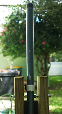
Due to the obvious deterioration of the antenna from lack of maintenance and from this area's highly corrosive seaside location, I've decided to remove the antenna from its second floor mount and to re-mount it in a more convenient location in my back yard. A main requirement of the this new mount was to provide a means to easily raise and lower the antenna when needed for maintenance and when adverse weather conditions threaten. Below is a photo of the new tilt ground-mount base for the GAP antenna that I've come up with.
The base is made up of two 8-foot long treated 2"x4"s that are sunk 3 feet into the ground. A 42" deep by 18" diameter hole was dug out, filled with 6" of rock then poured with concrete around the 2"x4"s. Three sets of 6" long carriage bolts were installed between the 2"x4"s below ground level to give the concrete something to grab onto other than the treated wood.
Above the ground, the 2"x4" were joined with a 4-foot piece of treated 2"x6". A 6-foot piece of schedule-40 1" galvanized water pipe (1.32" OD) is mounted inside the channel formed by the 2"x4"s and 2"x6" (backside of photo on the left).
The pivot-point for the tilt mechanism is drilled through the galvanized pipe near the top end of the pipe. The pipe swings on a piece of 3/32" stainless steel threaded rod secured with two nuts of the outside of the 2"x4"s. Another set of nuts is installed on either side of the pipe to prevent the pipe from wobbling when it swings in and out of the channel between the 2"x4"s. Refer to the photo to the right.
In the normal, upright position, the galvanized pipe is secured to the base mount using 3 stainless steel 1/4" U-bolts pushed through holes in the 2"x6". Two of the three U-bolts are visible in the photo to the left.
For the antenna to be lowered, the three U-bolts are removed and the antenna will be either walked or winched down to a horizontal position. (I'm considering installation of a hand-winching mechanism.) The top of the 2"x6" will prevent the antenna from swinging lower than a nearly-horizontal position. Refer to the photo of the unloaded swing pipe in the photo to the right.
The antenna will be mounted onto the top portion of the 1" galvanized pipe using a stainless steel mounting plate and U-bolts provided with the GAP antenna. The 5'x5' wire hoop at the base of the antenna will be installed after the antenna is raised into its vertical position. Likewise, the hoop will have to be removed prior to lowering the antenna into its horizontal position. By elevating the base of the antenna about 6' off the ground, the hoop will be positioned approximately 8' off the the ground and well above the heads of anyone walking in the yard.


No comments:
Post a Comment